Arduino Pro
The Arduino Pro is intended for advanced users who require flexibility and low-cost. It comes with the minimum of components (no on-board USB or pin header) to keep the cost down. It's a good choice for a board you want to leave embedded in a project. Please note that the boards operates at 3.3V (unlike most other Arduino boards, which use 5V); be careful when connecting external components.
Uploading Sketches
The board comes without built-in USB circuitry, so an off-board USB-to-TTL serial convertor must be used to upload sketches. This can be an FTDI TTL-232R-3V3 USB - TTL Level Serial Converter Cable, the SparkFun FTDI Basic Breakout Board, or any other USB to 3.3V TTL serial convertor.
If using the FTDI cable on Windows, you'll need to make one configuration change to enable the auto-reset. With the board connected, open the Device Manager (in Control Panels > System > Hardware), and find the USB Serial Port under Ports. Right-click and select properties, then go to Port Settings > Advanced and check Set RTS on Close under Miscellaneous Options.
In Arduino 0011, use the LilyPad Arduino entry in the Tools > Board menu to compile and upload sketches to the Arduino Pro (do not burn the bootloader to the Arduino Pro from Arduino 0011). Arduino 0012 will include specific support for the Arduino Pro.
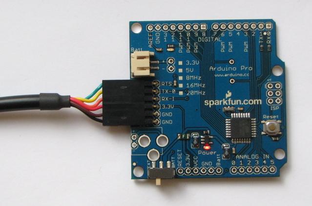
The Arduino Pro connected to (and powered by) an FTDI TTL-232R-3V3 USB - TTL Level Serial Converter Cable. The green and yellow wires align with the words "green" and "yellow" written underneath the pins.
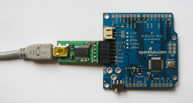
The Arduino Pro connected to (and powered by) a SparkFun FTDI Basic Breakout Board (prototype version) and USB Mini-B cable.
Power
The external USB-to-TTL serial convertor will power the Arduino Pro, regardless of the position of the switch. To use the board standalone, with no connection to a computer, it can be be powered by either a battery or external power supply (wall wart). Connect a LiPo battery (with JST connector) to the JST jack, or solder the + and - wires of a battery connector to the corresponding holes on the board. Alternatively, solder a DC power jack into the three large holes on the board, and supply between 4V and 12V (center positive). When the switch is in the "Batt" position, the board will draw power from an attached battery; when it is in the "Ext." position, power comes from an external power supply.
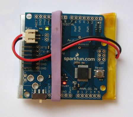
The Arduino Pro powered by a 2000 mAh LiPo battery from SparkFun.
Connectors
Any standard 0.1" spaced header can be soldered to the holes on the Arduino Pro. To use every pin requires two 6-pin header and two 8-pin headers. Bare wire can also be soldered directly to the holes. Note that the header spacing is compatible with Arduino shields. The text of the Arduino getting started guide is licensed under a Creative Commons Attribution-ShareAlike 3.0 License. Code samples in the guide are released into the public domain.